Frequently Asked Questions and Solutions for Call Recording
Which recorder is right for me?
 To choose a recorder, first determine the number of
lines required. Each line is an audio source, like a phone line, PBX port,
extension, radio or microphone. Lines can be "switched" for selective
recording from multiple sources.
To choose a recorder, first determine the number of
lines required. Each line is an audio source, like a phone line, PBX port,
extension, radio or microphone. Lines can be "switched" for selective
recording from multiple sources.
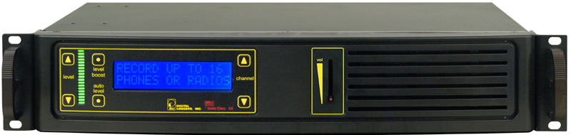
For just one line, Personal Logger is a match. For up to four lines, choose an easy-to-install network recorder with secure remote access. For 16-64 lines, the most cost effective solution is a USB recorder. Our new T1 logger is a great way to record up to 48 lines from a digital PBX or trunk.
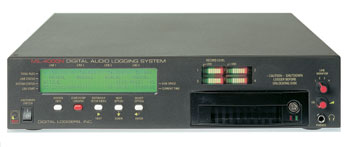
If you're a 911 PSAP, reliability is paramount. You'll want a serious 24-300 channel, network based recorder with a redundant fiber array. Disk arrays add performance and eliminate the potential for lost recordings.
For SMDR, ANI, or 911 ALI recording, download our free Call Detail recorder!
Logger Installation Tips
Three Basic
Ways to Attach a Recorder
Connecting Phones and Radios
Basic Phone Wiring
Recording Laws
Free Software Utilities!
Help by
Product
Single
Line Personal Logger
Four Line Network Logger
16 Line USB Logger
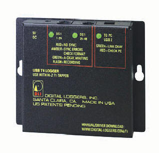
T1 and PRI loggers
Disk Array Loggers (24-300 Channels)
Personal
Loggers
Learn more - download a spec sheet. Download the manual.
Question: What is the latest version of Personal Logger?
Answer: The current version is 3.1.30.0 - released 3/14/2011. (Requires Windows 2000©, Windows XP© and DirectX 9.0c or newer, Windows Vista©, Windows 7©/Server 2003, Server 2008) Contact Techl Support if you need an updated version. Please note that there are now additional settings in the preferences section.
Question: Is Personal Logger Windows 64-bit Compatible?
Answer: Yes.
Question: The calls are too loud / quiet. How can I change the volume?
Answer: The
microphone usually can be adjusted from within the preferences menu. however,
the preferred method is listed below:
To adjust the microphone level in Windows Vista or Windows 7, right-click on
the
speaker
by
the system tray and select Recording Devices.
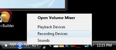
Alternatively, press the Start button, type "mmsys.cpl" in the search box, then select the Recording tab.
Next, select your microphone from the devices listed.
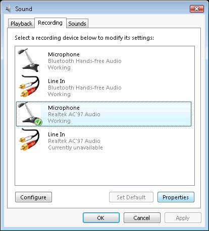
Select Properties and adjust the level as needed.
If the levels are too low, go to the Custom tab and select "Mic Boost" , then readjust the
levels.
Question: There’s no audio – Help!?
Answer: Try one of these three common solutions!
1. First, check your microphone input level controls. If you have not used a microphone on your PC, chances are the microphone jack is turned off. Adjust the device properties using the Windows audio control panel. Be careful – there are two screens, one for recording properties and one for playback properties. Switch between them by using the “view” menu. For each version of Windows, there is a slightly different way of checking and changing the Recording Properties.
Windows 2000/ME/XP:
- Right click on the Speaker icon in the tool bar
- Choose Adjust Audio Properties
- Under the Audio Tab - Recording Device click on Volume
...- Make sure that the Select box for Microphone has a check and that the volume slider is raised.
- Test the audio level. This window can remain open while testing.
- If the volume is still too low, press the advanced button and enable mic boost. You may need to select Options/Advanced controls to display the button. Not all systems have this advanced capability.
2. After you're sure your microphone input is working, check the cables, and make sure that you are using the proper “Y” connector and cable. The different types of connectors are described below.
3. Third, make sure the output of the logger module is connected to the “MIC” jack on your PC, not to the “LINE IN” jack.
Question: What are the different connectors for?
Answer: We want you to have everything you’ll need. There are two types of connectors. One is a larger jack, called an RJ-11 jack which is used to connect to outside lines. Look carefully and you’ll see a second type of jack which is slightly smaller. The small “Y” connector and cable jack are used for connecting phone handsets. If you've accidentally used the small connector on an RJ-11 wall jack, you may have an unreliable connection, or no connection at all. If the connector looks loose, switch to the larger plug.
Question: How do I enable Outlook Integration and Internet lookup to trace calls?
Answer: To fully enable Outlook integration and call tracing, you'll need the following:
- A phone line with Caller-ID
- A live (always on Internet connection)
- Microsoft Outlook
- An outside line connection
- Your area code must be properly entered in Windows
- All Phone Number Lookup features must be enabled.
In the preferences window, under the 'Phone Number Lookup' section, check the 'I have Caller ID' box, the 'Enable Internet Lookup" box, and the 'Enable Outlook Lookup' box.
The 'Area Code' section indicates the Area Code you are located in. The value defaults to the location information from the 'Modem' control panel. You can change this value if the Area Code is inaccurate or you travel with this computer.
Question: How can I eliminate stuttering in the recordings?
Answer: If the recording sounds "stuttered" when playing back, you either need to upgrade your sound card drivers, or you're running out of "horsepower" for recording. If drivers are the issue, try your PC manufacturer's web site. If performance is an issue, a higher performance PC will help. You can also get more performance by closing unused applications, such as Real Player and Anti-Virus software while you are recording.
Question: I sound louder than the caller. Why?
Answer: This is a normal effect when recording from an outside phone line. Your telephone includes a device called a “hybrid duplexer” that makes your voice louder to compensate for the loss of signal in the lines going to the phone company. You can minimize this effect by checking “normalize recorded files” under the “general” tab in the properties box. You can also eliminate most of this effect by switching to a handset connection. Note that you won’t receive caller ID information if you record from a handset.
Question: What's the hidden mode? How does it work? What are the legal implications?
Answer: If you selected the 'Hidden' mode installation when setting up Personal Logger, there are three things you should be aware of:
1) Hidden mode applications must operate in VOX mode. The application will not record continuously when hidden.
2) You may need to access the application to change settings. To do so, press the key combination CTRL-ALT-HOME (all keys simultaneously) and the application will appear. To make the application disappear again, select 'Recording|Exit' or press the 'X' button in the upper right corner of the window. A message box will appear. To stop the application completely, press the 'Exit the Application' button. To hide the application again, press the 'Re-hide the Application' button. To return to the application, press the 'Return to the Application' button.
3) Hidden mode is provided to reduce the clutter on your Windows desktop. All recording laws must be observed, and this feature is not intended and should not be used surreptitiously. Read more about recording laws here.
Question: How do the recording controls work? What do the buttons do?
Answer: Here's a summary of the controls on the main Personal Logger screen. Press F1 for more detailed help when running the application.
Question: How do the playback controls work? What do the buttons do?
Answer: Here's a summary of the controls on the main Personal Logger screen. Press F1 for more detailed help when running the application.
| Play Button | Starts playing the selected call |
| Stop Button | Stops playing a playing call |
| Pause Button | Pauses a playing call |
| Jump to Start Button | Jumps to the start of a playing call |
| Jump Back 5 Seconds Button | Jumps backward 5 seconds in the playing call |
| Jump Forward 5 Seconds Button | Jumps forward 5 seconds in the playing call |
| Email WAV File Button | Allows you to email the selected call |
| Save WAV File Button | Save the selected call as a WAV file |
| Delete Button | Deletes the selected call (or press DEL key, or select from context menu) |
| Output Device Selector | Select the sound card you wish to play calls to. This appears only if you have more than one audio output device installed.. |
Question: How can I integrate Personal Logger with Microsoft Outlook?
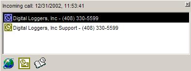
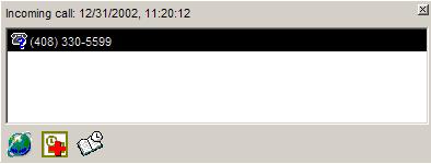
Answer: Glad you asked. This is one of the best features in Personal Logger. If you have Caller ID (CID) service installed by your phone company -and- the personal logger is connected to this outside line, you can analyze incoming calls for CID and display contact information on the screen. Remember, this feature won't work with a handset connection. You'll need to be connected directly to an outside line with CID to use this feature. Here's how it works:
When an incoming call comes in, Personal Logger will analyze the recorded call for CID information within 10 seconds. If CID is detected, Personal Logger will then look up the phone number in Microsoft Outlook Contacts (if you have set the 'Enable Outlook Lookup' preference - see below) and a small window will open at the bottom left of your screen that looks like this:
 |
or |
 |
| If the number is in Outlook |
If the number is NOT in Outlook |
If the phone number matches more than one entry in Outlook, then they will all show up in the list (as shown).
Question: A strange program pops up when I click on files with an .au or .wav extension. Why?
Answer: The default (and often best) player for these files is the Microsoft Windows Media Player.
Question: How can I find and play calls?
Answer: Select View from the toolbar of the Personal Logger Application and click on Show the Instant Replay Window. By selecting one of the headers, your recordings can be sorted by date, time and length of call as well as by any Notes you've made for the recording.
For more advance features like Caller ID lookup and report printing, use our Evidence Builder software. Use our Evidence Builder Software for printing reports, scanning for caller ID and outbound numbers, and tracking agent performance. It’s also ideal for law enforcement applications where evidence tapes must be prepared from several recording sources.
Question: How can
I include recordings in a document?
Answer: Using Microsoft Word, choose the “Insert
-> File" option and use the browse button to locate the file you want in the correct date folder
and by time-stamped file name.
Question: Windows gives me an error message: "The specified format is not supported or cannot be translated." How can I update Windows media player?
Answer: To download the latest media player upgrade, run "Windows Update", or visit the Microsoft web site to for the latest update.
Question: Why don't my recordings go through e-mail?
Answer: There may be a message size limit on your e-mail box, or on the recipient’s e-mail box. Here are two workarounds:
1. Send shorter recordings. Use the start/stop buttons to break long calls up into shorter segments.
2. Compress your recordings using Windows recorder or Compactor. You will lose sound quality when doing this, so you may want to make a backup of the original file before compressing it.
Question: When is it legal to record?
Answer: There’s no short answer here. Federal laws require that at least one party being recorded consent to the recording. Some states (such as California) require that both parties consent. Consent is implied when a caller stays on the line after hearing an announcement or statement such as “Your call may be recorded for quality assurance”. Consent is not required where there is “no legal expectation of privacy”, such as when calling 911. Businesses must post warning signs when recording from microphones in some states. Additional federal regulations apply to recordings made from radio receivers and to facsimile recording. We’re not lawyers, and these laws change all the time, so check your local regulations before recording. Hyperlink to our favorite web site with recording laws: "Can We Tape?"
Question: The recording level is low. How can I adjust it?
Answer: Make sure the output of the logger module is connected to the “MIC” jack on your PC, not to the “LINE IN” jack. Check the levels in the Windows Audio Control Panel.
First, select "recording properties" in the "view" menu. Make sure the "select" box is checked under the microphone level control bar in the recording controls. Make sure the slider bar is raised up.
Next, select "playback properties". Check the "mute" box under the microphone level control bar to prevent feedback. This will prevent the audio from being played on the speaker while it is being recorded.
Question: What is CID? What is ANI? How can I record Caller-ID?
Answer: CID stands for Caller Identification. It is also known as "Automatic Number Identification", or ANI. All DLI loggers will record caller ID when connected to an outside line which has this service. First, contact your local phone company and ask them to provide caller ID service on the line you are recording.
Question: What is ALI? How can I record ALI?
Answer: ALI stands for Automatic Location Identification. ALI is transmitted to 911 call centers and emergency service dispatchers. Local telephone companies keep a database which cross references telephone numbers to physical addresses. These addresses include pay phones and numbers unpublished in public directories. This data is normally provided using Bell-103 FSK at 300 Baud or 1200 Baud FSK in a format similar to CID. The local phone company normally provides a modem and a terminal (or PC) to review this data stream at the dispatch site. To keep a log of this data, an additional serial port connection may be made to the network logger.
Question: How can I create a .WAV file? How can I email a call? How can I delete a recording?
Answer: Simple. First, open the instant playback window. Select a completed call by highlighting it with the mouse. Three buttons above the call list will become active. Use the first one to email the call as a .WAV file, the second to save a .WAV file, and the third to delete a call.
Question: How can I compress recordings? How can I reduce the size of .au files? What is Compactor?
Answer: The .au format records at a rate of 64Kbps, or 8KBps. To reduce the size of an audio file, you need to use audio compression, which will reduce the quality of the audio. The smaller the file, the lower the quality. 64Kbps u-law is standard telephone quality. Compression ratios as high as 8:1 produce audio files which are still understandable. You can open a file using Windows recorder and save it in a different format to compress it and see how it sounds. DLI customers can download a free utility called Compactor.EXE which will automatically compress files. Compactor will convert your u-law format recording files to a more efficient recording format called ADPCM, which reduces file size by 50% to 32Kbps.
Question: Can Compactor be run from a command line? What are the switches?
Answer: Yes, compactor can be run from a command line or as part of a batch file. The command line switches are:
/path <path> - specifies which folders you wish to compact. This command line switch is required.
/subfolders - specifies that you want the app to compact subfolders below specified path, as well
/hidden - the app will not show itself, do the specified compaction, and end when done
/remove - deletes the original .au files automatically after compression
/all - compacts all .au files found (not just older ones).
/age <number of days> - compacts only .au files greater that 'number of days' old.
NOTE - if both /age and /all are specified, compactor will use the last switch in the command line
/priority <idle, low, normal, high> - this specifies the priority that the compaction process should run under. An 'idle' priority process will only run when other processes do not need the CPU, 'low' will run slightly more often, 'normal' will run in contention with most other processes on the system, and 'high' will make the compaction take precedence over most processes on the system.
Here's an example:
C:\>Compactor.exe /path "C:\Logger Files" /age 30 /hidden /remove /subfolders /priority idle
This will compact all call files in 'C:\Logger Files' and its subfolders of greater or equal to 30 days old. The application will run hidden, remove the original call files, and run at an idle priority (meaning it will only run when no other processes need access to the CPU).
NOTE - you may use dashes (-) instead of forward slashes (/) on all switches if you wish.
Question: How can I adjust the voice activation (VOX) operation? How does the logger start and stop recordings?
Answer: VOX is synonymous with Voice Activated Switch. The Voice Activated Switch in the Personal Logger controls the start and stop process which separates calls into individual files. There are three settings which affect the VOX operation in the Personal Logger program. These are found in the lower right corner of the main Personal Logger window. The first is a starting control called the sensitivity. Adjust the sensitivity by clicking first on the Voice Activation tab under recording properties. Moving this slider bar will adjust the sensitivity up or down and move an arrowhead ^ under the VU meter. When the meter reaches the arrowhead, recording will start automatically. Adjust the arrowhead so it is just to the right of the meter level when the phone is on-hook.
If you experience "false starts" and see files with clicks and pops in them, there is a second adjustment. To reduce false starts, you can adjust a second setting called the "transient noise length". This setting adjusts the amount of time which must elapse with the recording level above the occur before the recording starts. Increase the "transient noise length" to eliminate small recordings with clicks and pops.
There's a third setting called the timeout which controls the amount of silence that must be detected before the recording file is closed and another file is started. The exact adjustment is a matter of personal preference. Most customers find that between 20 and 30 seconds for phone calls (10-20 seconds for radio calls) works well.
Four Channel Network Loggers - Instant Web Access!
Learn more - download a spec sheet. Download the latest manual.
Question: What is the latest version of firmware for the MIL4000N?
Answer: The current version is 1.6.0 - released 03/18/2010. Changes can be viewed here. You can determine the current version of your logger by pressing the System Info button and reading the Image Version. You can also check the version by using the MIL4000N Remote Utility (1.2MB). This utility will download the latest binary. If you have a proxy server or a firewall preventing the utility from retrieving the latest binary you can download the latest binary here. (7.3MB). It must be located in the same directory as Mil4000nUtil.exe. If you are running Windows NT©, Windows 2000© or Windows XP©, you must be an administrator to use this utility.
Question: I'm seeing noise on all four lines? Why?
Answer: This is caused by a bad ground connection. Check your power cord and outlet. Try moving the plug to a different outlet. Use a 3-bulb tester to confirm you have a good ground connection. If you're in a phone room, attach a frame ground lead to the ground bus bar.
Question: How can I delete calls on the logger?
Answer:
There are only three ways that calls can be deleted from the MIL4000N logger:
1. When the free disk space drops below 10%, the logger will automatically delete the oldest calls,
one day at a time, until there is 10% or more space free.
2. You can rename a line. Shortly thereafter the old folder (and calls) can be deleted from the configuration
page.
3. Delete all of the calls on the drive
However, if you wish to only delete certain calls, that is not possible.
Question: My logger keeps stopping (going inactive). Why?
Answer: The logging program is designed to immediately restart if any error occurs. If "Autostart Logging" is "No", the application will not resume logging. Go to the Logger Configuration page and set "Autostart Logging" to "Yes".
Question: How do I install the MIL4000N?
Answer: You'll need to make two connections - one to your phone system or radios to connect the incoming lines, and another to your LAN to allow playback. Please read the manual for detailed instructions.
Question: What is the IP address of my MIL4000N?
Answer: You can see the IP address by pressing the System Info button three times. The IP address will show up on the display. Alternately, you can download the MIL4000N Remote Utility. This utility scans the network for MIL4000N loggers and provides hyperlinks to all units. Your logger must be in the same class-c subnet to use this utility. In other words, the first three segments of your IP address must be the same as the logger. If you are running Windows NT, Windows 2000, 2003, XP, or .NET you must be an administrator to use this utility.
Question: I get access denied errors when backing up across the network. How can I fix this?
Answer: Some files can't be copied because of permissions
issues. For this reason you cannot simply drag-and-drop files to your computer from the logger since
windows hits a problem, then quits. To avoid this, specify *.au when performing a backup with an alternate
program.
If you are copying from the command line, you can use the /C (continue and ignore errors) option for
XCOPY as well since a file may be in use:
e.g.: XCOPY L:\*.au /S /C /I D:\LoggerBackup
Question: I can't see the logger on the network with my Windows 2000 or Windows XP computer. Can I fix this?
Answer: The MIL4000N is a Linux based system and uses SAMBA to share the files. Therefore, NetBIOS over TCP/IP must be enabled in the Advanced section of the TCP/IP settings as shown below.
If you have a firewall between your computer and the logger, you must have the following ports open between the two units.
| Name | Port | Description |
| netbios-ns | 137/tcp | NETBIOS Name Service |
| netbios-ns | 137/udp | NETBIOS Name Service |
| netbios-dgm | 138/tcp | NETBIOS Datagram Service |
| netbios-dgm | 138/udp | NETBIOS Datagram Service |
| netbios-ssn | 139/tcp | NETBIOS Session Service |
| netbios-ssn | 139/udp | NETBIOS Session Service |
Note: These ports are only required if you intend to map a drive letter to the MIL4000N Logger.
Question: Why do I need to press and hold the "Next" button before I can upgrade the logger?
Answer: This is a security feature. The fact that the logger has been authorized to accept an update, prevents anyone having a current Update Utility from disrupting call recording and possibly reset your setup to factory defaults. Please note that the MIL4000N Update Utility will only reset to factory defaults will not "downgrade" your logger to an earlier revision.
Question: What is the HOSTS file for and why do I need to change it?
When attempting to access a named Internet URL,
the web browser requires an IP address. The HOSTS file is the first place that the browser looks to
determine the IP address of the web site or location. If the name is not found, it then asks the DNS
servers for the IP address of the location. Since some loggers may be behind a router or firewall and
we use a specific port to access the configuration functions of the logger, we must use the Internet
name system. The MIL4000N Remote Utility
can will automatically update the hosts file for you after scanning for loggers.
Note: As of version 1.5.0, using the Internet name system is optional and turned off by default.
Question: There are two inputs to each line on the back of the logger. Which one do I plug the phone line into?
Answer: Either port will work. They are connected in parallel (pass through). You may connect one port to an outside line, and the other to a PBX, phone, or other CPE.
Question: Why do I get an "access denied" error when attempting to use Evidence Builder Software?
Answer: Be sure that you have added your user name and password to the logger.
NEW! T1 and PRI Loggers (24-48 Channels)
Learn More - Download a spec sheet or browse the installation guide.
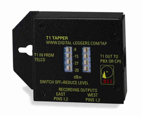
Question: How can I bridge a T1 without taking it down? How can I connect the logger without reprogramming my PBX?
Answer: Glad you asked. That's the beauty of this product. With other loggers, you'll encounter "stub problems". This occurs when the customer PBX disconnects from the T1 or experiences noise problems because you connected a logger directly across the line. The T1 span becomes overloaded, and signal integrity is lost. We have a solution. The "T1 Tapper" goes between the PBX and outside line. T1 data flows smoothly through it, and the customer equipment is unaffected. Just place the tapper between the PBX and the T1, and run a cable from the Tapper to the logger. No PBX programming knowledge is required in this configuration. If you have DID lines or CID, the numbers called will appear in Call Analysis Software. Outbound DTMF (touch tones) are also decoded. With this feature, you can easily sort calls by inbound or outbound number dialed.
Question: What kind of T1 lines are supported?
Answer: The logger supports all US standard T1 lines as well as Japanese formats. AMI, B8ZS, SF, ESF line codes are supported. FT1 lines will work fine, just disable logging on the data and unused channels.
Question: How many channels can I record?
Answer: Since the logger has two T1 framers, you can record up to 48 channels. If you have a PBX programmed to output audio via a T1 card, each of the 48 channels can be recorded individually. If you are bridging an outside T1 span in half-duplex mode, you can combine the audio from the East and West sides of the line automatically. In this configuration, you'll record 24 channels.
Question: Does it support PRIs?
Answer: Yes, ISDN PRI's are supported. You'll record 23 channels per trunk on a PRI. The 24th channel carries signaling and can be recorded to a raw data file. VOX operation is used for start/stop control. DTMF and CID are currently only decoded when transmitted in the voice band.
Question: Where can I learn more about T1 ?
Answer: Here's an excellent book by Matthew Gast, T1 - A Survival Guide
Question: How can I connect to my PBX in "loopback" mode?
Answer: Looping a T1 port card on your PBX will let you connect the logger in 48-channel mode. You may then route speech paths between the T1 DS0 channels and voice paths inside the PBX, such as extensions, outside trunks, or voicemail ports. Doing so allows you to record extension, trunks, and voicemail ports in a separate directories. PBX configuration and programming knowledge is required to do this, and the configuration procedure and available features vary by PBX. On a PBX with internal CSU/DSU on the T1 line card, you can usually run in "loopback mode". A hardware loopback plug is required on some systems. Only two wires per T1 channel are required in this configuration, since East=West and E+W are combined inside the PBX. You can stub the port directly and the -3dBm attenuation will not affect the logger. Be sure to disable the "+20dBm gain boost" in the logger configuration when running in separate mode without a tapper.
Question: How can set my Avaya T1 port in loopback mode to run the logger in separate mode?
Answer: On an Avaya PBX with internal CSU/DSU, the loopback "feature code" is 0x4140.
Question: How can I record from my Asterisk PBX in "separate mode"
Answer: In Asterisk, you will need a monitor command to redirect the recording output to the T1 port.
[from-pstn-pri]

exten => _X.,1,Monitor(,,b)

exten => _X.,n,Dial(DAHDI/g11/${EXTEN})
If you receive the "circuit is busy : CONGESTION" error, you'll need a loopback plug.
Question: How many T1 loggers can I connect per PC?
Answer: One per server (a maximum of 48 individual DS0 lines in separate mode, or 24 combined E + W lines in combine mode) with the basic software package.
Question: Is FT1 supported? How can I select a particular DID channel from within a T1 line?
Answer: When bridging an outside T1 line, you can individually select the timeslots you'd like to record. Fractional T1s are supported by disabling the unused timeslots. If you have DID speech paths to individual timeslots, these DIDs will be recorded in separate directories by default. If you have a "supertrunk" T1 with more DIDs than timeslots, you first record all pertinent time slots. After recording, you can select specific DIDs for review and replay by using our Evidence Builder software. This software is included free with all DLI T1 loggers.
Fibre ChannelNetwork Loggers (24-300 Channels) - Ultra Reliable Call Storage!
Learn more - download a brochure. Download a users guide.
Question: What are my call storage options?
Answer: Just about anything you'd like. The logger can record to local or remote network drives. For the ultimate in reliability, we recommend Fibre Channel or Infiniband disk arrays. These disks can be configured as RAID systems with redundant power supplies. Contact DLI for more information.
Question: How can I back-up recordings?
Answer: There’s no magic here. Since our system is "open", any commercial backup software can be used. Here are four popular choices:
- For enterprise backup, Veritas Backup Exec is the most powerful application. Most larger enterprises and 911 call centers choose Veritas.
- For ease-of-use, Windows Backup is best. You can back up to DVD, AIT, or DLT drives and remove the media for archival storage.
- Another great backup option is a removable USB 2.0 hard drive, available directly from DLI. This can be attached to the file server and a "drag and drop" will quickly back up your files. If you already have a network backup system, you can just add the logger storage array to your backup list. With Fibre Channel, you can also consider using an extra hard drive as removable backup.
- If you'd like to back up automatically to a local DVD burner, download our free backup utility (for DLI network loggers only.)
Question: What is a u-law (pronounced "mew-law") file?
Answer: u-law
is a non-linear coding system used by the telephone company to transmit audio in a digital format.
u-law operates at 8,000 samples per second in an 8-bit format. Because this is a logarithmic
format, it is more efficient than linear coding formats, such as the popular .WAV format. u-law
encoding is technically not a form "compression". Rather, it is a way of adjusting
the sampling characteristics of the Analog-to-Digital conversion process to match the logarithmic sensitivity
of the human ear. u-law encoding is typically referred to as "companding".
When an 8 bit u-law sample is sent, one bit is used to give the polarity of the signal (1 for positive,
0 for negative). The remaining 7 bits correspond to the logarithmic quantization of the sample.
An 8-bit u-law file offers performance equivalent to a 14 bit linear file. The less efficient
.WAV file format is the most common audio format used in transferring audio between PCs.
Question: What editing software do you recommend for u-law files?
Answer: Sony Sound Forge is
one of the many programs that can be used for editing .au files.
Question: What is "instant replay" or "real-time playback"? How can I do this? What causes delays in playback?
Answer: These terms refer to the playback of an audio file while it is being recorded. In most applications, minimizing the time between recording and playback is desirable. Delays in playback result from four main causes:
- File Locking
File locking can prevent a file from being played at all while it is being recorded. Most versions of Microsoft Media Player require that a file be locked for exclusive access. This is why Media Player is often unable to stream audio from .au files while they are recording. To bypass this limitation, choose another player. Other players, such as "Sound Forge", "Real Player", and "Quick Time" can stream audio for simultaneous playback by opening files for non-exclusive use while they are being recorded. During the time that an .au file is being recorded, the file length in the header must be set to 0xFFFF for proper playback. DLI has an instant playback utility for network loggers which uses Direct-X for high performance. Using Direct-X allows you to mix several files together for simultaneous playback. Windows users can download the free DLI Real Time Player here. - FIFO and DSP Delays
A delay is inherent in processing an incoming signal using a Digital Signal Processor (DSP). This delay is can be extensive when CELP or other predictive coding is applied to the incoming data. DLI loggers have approximately 100ms (1/10th of a second) of FIFO delay. Dialogic cards, such as those used by Mercom or Voiceprint typically have a 250ms delay. Dictaphone (remarketed Eventide) recorders typically have a 200ms delay. - Network Delays
Since Ethernet is not a real-time network architecture, delays are present when audio is streamed over Ethernet. These delays can range from a fraction of a second on a fast LAN to 20 seconds or more on a WAN. Excessive traffic on a network can cause packet loss, which can multiply these delays. Some networks have quality-of-service "QOS" settings which can be used to minimize these delays. These settings are used with mixed success in IP telephony. - Prebuffering Delays
Network delays are compensated for by the player, which reads ahead and buffers data. Players use a technique called "prebuffering" to eliminate network delays and reliably stream audio. The amount of delay between recording and playback is proportional to the size of the buffer. In some programs, this buffer size is set automatically. To adjust the buffer size in Media Player, click on the Tools Menu, then select the Options tab and enter the new buffer size (in seconds) under the Network Buffering box. One second of .au data equals 8kB of buffer size.
Question: How do I convert u-law files to .wav (Wave) format? How can I convert a u-law file to save it on a CD?
Answer: Creating
.wav files is easy. Using Personal Logger, just click on the file button to save in .wav format.
Using Call Analysis Software, select the "save as .wav" option in the first menu. You
can use "Cool Edit" to convert virtually any audio format into the 44.1KHz format used in
standard audio CDs. To do this in Cool Edit, first open the .au file. Then press F1.
Select 44100Hz sampling, and stereo. Then save the file and burn it on an audio CD.
Question: How do I log serial data from an ANI, ALI, SL1, or SMDR source.
Answer: This data is usually sent at 1200 or 9600 baud using a standard serial port. To connect a DTE serial source to a PC, use a "straight through" DB-9 to DB-25 serial cable. To "bridge" a serial port, you need just two wires, ground and serial out. Connect these to an RS-232 port on your DLI logger and you will have a serial data stream which can be recorded. There are a number of applications, including Hyperterminal which can record this data, but we recommend this free call detail recorder. Be sure to set your serial port to the correct baud rate. You may also need to jumper the DSR and CTS pins on the serial connector so this data will flow from your PBX. For most applications, a searchable text file is the best output.
These utilities are provided free-of-charge to DLI customers. They will operate only in conjunction with DLI recording products. Click to download the utilities, and feel free to call for technical support.
Wiring Basics for Logger Installation
Question: How do I connect a radio?
Answer: Manufacturers use different radio connectors, so you'll first need to locate a mating connector. After that, it's a simple two-wire connection to the logger. You can directly bridge across the speaker, headset, or earbud.
Question: How do I connect the logger to a PBX?
Answer:
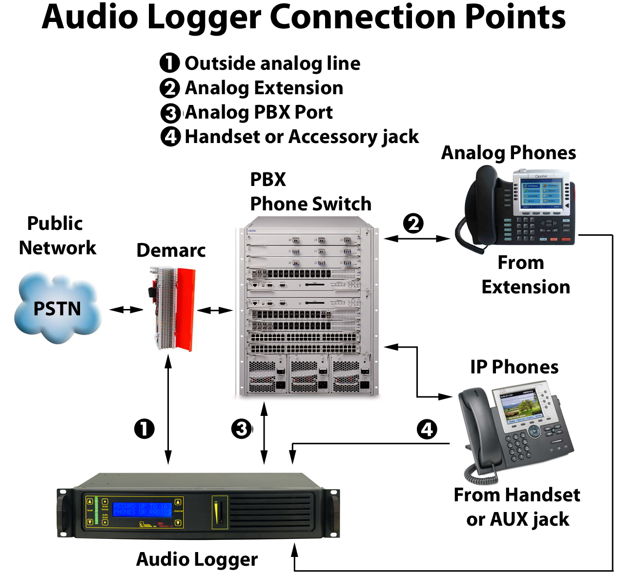
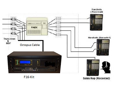
These are the three best ways to link your logger to the outside world:
1. You can record from incoming lines. This lets you hear the recording from the outside party’s perspective. It is commonly used for quality assurance recording. This type of connection is not commonly used in agent analysis or 911 call center recording. Most of these applications use the handset tap (below).
LOGGER CONNECTION TO INCOMING ANALOG LINES
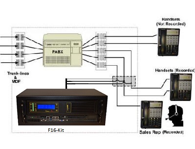
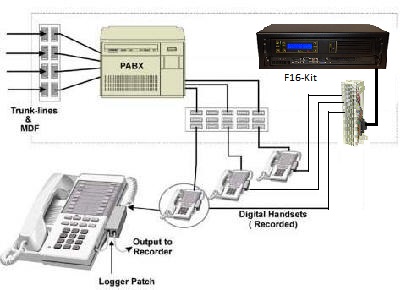
2. You can tap the handsets or analog station sets directly. This method allows you to hear the recording from the agent’s perspective. If you are recording in an E-911 dispatch environment, this connection will record things from the dispatcher’s perspective, and the recording will typically include the phone conversation, radio dispatch, etc. Essentially, you will hear everything the dispatcher hears in the recording. Handset taps may be connected to the analog output of the phone, or run through a Digital to Analog (D/A) converter. They may also be connected by a digital tap card, such as those sold by Intel. When recording from a handset, Caller-ID will not be stored in the recording files. You may want to use handset taps in conjunction with SMDR recording. You can record SMDR data directly on the logger by using an RS-232 cable.
LOGGER CONNECTION TO ANALOG STATION SETS
LOGGER CONNECTION TO HANDSETS (ANALOG OR DIGITAL STATIONS)
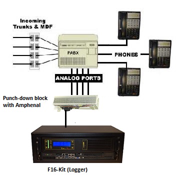
3. You can connect to a PBX port. This is the most common method of connecting a logger in large installations (100+ channels). One advantage of this connection scheme is that the PBX can be used to switch the recorder to a large number of lines. Another is that the logger can be switched to any recorder outside trunk or inside extension. Think of this method as “conferencing in” the logger with either an outside caller or an inside extension. This method requires an programmer familiar with your PBX. The programmer creates a "speech path" between the logger and the auto source.
LOGGER CONNECTION TO PBX ANALOG PORTS (ANALOG OR DIGITAL STATIONS)
Question: What's a demark point?
Answer: A "demark point" is a single point of entry into a building for CO wiring. In most situations, the customer is responsible for all wiring after the demark point, and the phone company is responsible for all wiring before that point. A lightning arrestor is typically installed by a phone company near the "demark point."
Question: What's a CO (Central Office)? Where does my phone line go?
Answer: A central office is a local switching facility which routes voice and data over telephone lines. It is typically located within the center of a city. The phones in your home or office connect to a Central Office and are routed from there through the worldwide Public Telephone Switching Network (PTSN).
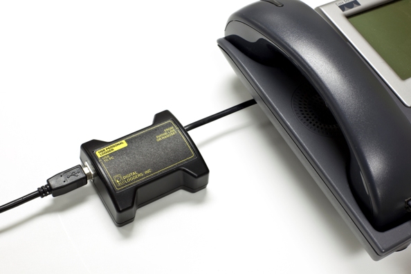
Question: What's a handset jack? How do I connect a logger to it?
Answer: A handset jack is a small 4 pin connector which carries the speaker and microphone signals from your telephone to your handset. This is a good place to connect an audio logger, since all your incoming conversations may be recorded at this point. A typical signal level to the handset earpiece is -20dBm, and this is adequate for most logging applications.
To connect to a handset, use the handset splitter supplied with your logger and the small handset jacks. Pay careful attention as these jacks look very similar to the RJ-11 and RJ-12 jacks described below. Putting a handset plug into a larger RJ-11 or RJ-12 jack will result in an unreliable connection.
![]()
Question: What's an RJ-11 jack? How do I connect a logger to it?
Answer: Most analog phone lines use an RJ-11 jack and plug in a single line configuration. An RJ-11 jack has four wires and is called a 4P4C connector, since it has 4 conductors in 4 places. Wires on an RJ-11 jack are colored black, red, green, and yellow. The center pair (red and green wires) is used to connect the ring and tip side of a single phone line. The yellow and black wires are used for either a second line. The pinout for an RJ-11 jack is as follows:
Color Pin Signal
Black 1
AC Power or Tip (Line 2)
Red 2
Ring (Line 1)
Green 3 Tip (Line
1)
Yellow 4 AC Power
or Ring (Line 2)
The photo below shows a 6 pin RJ-12 jack on the left, and a 4 pin RJ-11 jack on the right.
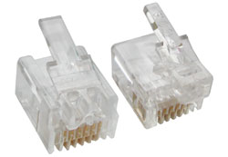
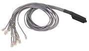
If you are connecting an RJ-21X to an RJ-11 jack, you can use either a rack mount patch panel with 24 RJ-11 jacks, or an "harmonica" or "octopus" cord. An Octopus cord has a single 50 pin AMP connector (RJ-21X type) on one end, and 24 RJ-11 type plugs on the other end.
OCTOPUS CORD
Be careful not to confuse the RJ-11 plug with a handset plug. They look almost identical, but inserting a handset plug into an RJ-11 or RJ-12 jack will give you an unreliable connection.
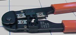
You'll find that a 6P6C crimp tool will work fine for both RJ-11 and RJ-12 connectors. You'll need a different tool for handset connectors and RJ-45s.
Question: What's an RJ-12 jack? What's an RJ-14 jack? What wire colors connect to each pin of the jack? How do I connect a logger to it?
Answer: Most analog phone lines use an RJ-11 jack and plug in a single line configuration, but there's a similar connector called an RJ-12 or RJ-14 which expands the capacity of this jack to 6 pins. The 6P6C RJ-12/14 jack has the same physical outline as an RJ-11 jack, but can contain 3 pairs of wires. An RJ-12/14 plug will fit into an RJ-11 jack and vice versa. If you insert a 4-pin RJ-11 plug into a 6-pin RJ-12 jack, you will be connected to pins 2,3,4 and 5 of the RJ-12 jack. The "translation" of pin numbers when mismatching jacks and connectors can lead to confusion.
DLI loggers use pins 1 and 6 of the RJ-12 to send power to remote microphones. To wire an RJ-12 jack in a single line configuration, just make sure the red and green pair is connected to pins 3 and 4 of the jack for line 1, or pins 2 and 5 for line 2.
When two lines are connected to an RJ-12 or RJ-14, they should be wired as follows:
R1 and T1 are "ring and tip" for line 1. R2 and T2 are "ring and tip" for line 2.
| Jack Positions |
USOC RJ11 |
USOC RJ12/14 |
|
| 2 | wht/org | ||
| 3 | blue/wht | blue/wht | |
| 4 | wht/blue | wht/blue | |
| 5 | org/wht |
Question: What's an RJ-25 jack? How do I connect a logger to it?
Answer: An RJ-25 jack is a standard 6-pin, 3-pair telephone jack. It's wired as shown below:
R1 and T1 are "ring and tip" for line 1. R2 and T2 are "ring and tip" for line 2, and so on.

| Jack Positions |
USOC RJ25 |
| 1 | wht/grn |
| 2 | wht/org |
| 3 | blue/wht |
| 4 | wht/blue |
| 5 | org/wht |
| 6 | grn/wht |
Question: What's an RJ-31x? How do I connect a logger to it? How do I test it?
Answer: Most security lines use a special type of jack, called an RJ-31x. It is an "exclusion type" dialer jack. It is typically a Leviton style 8 pin jack, but similar wiring may be done on KT-66 or W110 punch down blocks. Each 66 block handles 3 lines in the RJ-31x wiring configuration, and all the pin order matches the order of the RJ-31x jack pins. The first jack connects to pins 1-8, the second to pins 9-16, and the third to pins 17-24. This type of wiring is commonly encountered in 911 call centers and in most commercial alarm installations. RJ-31X jacks are required for many security and fire alarm systems that provide exchange to alarm reporting devices. In an RJ-31x installation, the phone line is wired in series through the RJ-31X; from there, tip and ring pass through the dialer. A normally closed relay opens if the alarm is activated, seizing the circuit for alarm use, while temporarily disconnecting lower priority equipment (such as a house phone) to prevent disruption of the dialing sequence.
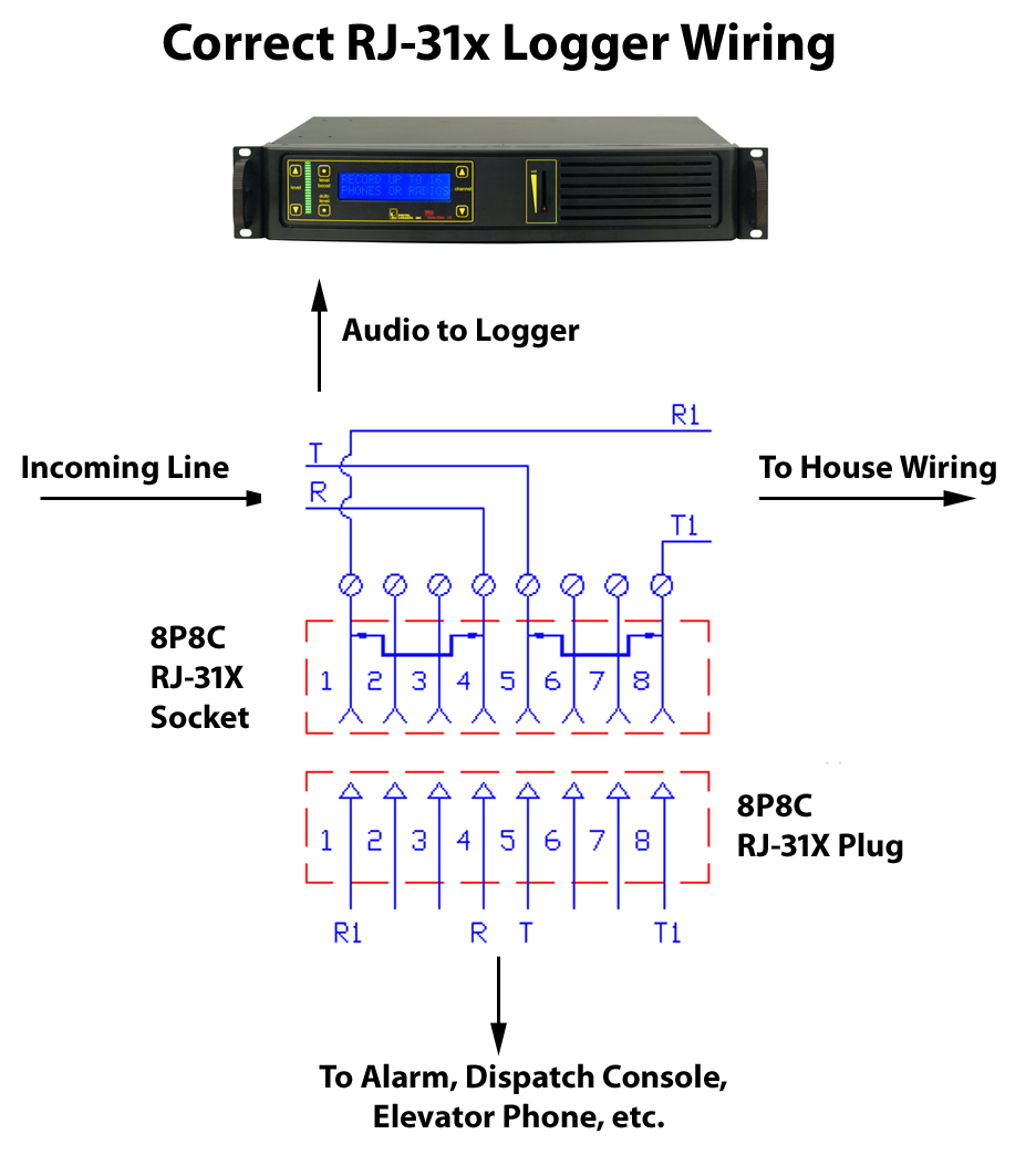
The most common RJ-31x installation is an 8-position, non-keyed miniature jack with shorting bars across terminals 1-4 and 5-8. Inserting the modular plug lifts the contact wires away from the shorting bars, extending the tip and ring circuit to the series leads going into the alarm device. The audio logger connects to pins 4 and 5 of the jack in a "bridging" configuration. When the plug is removed from the jack, metal tabs inside the RJ-31X provide direct connection of tip and ring back to the other locations, bypassing the alarm device. This design lets the dialer control the line for exclusive use when in alarm mode. It also helps isolate defective or improperly wired equipment by disconnecting the RJ-31x plug to route tip and ring directly to lower priority equipment. In some installations, a 911 dispatch console will be rerouted to a backup console by connecting the backup console to the "house phone" connections on pins 1 and 8.
Some technicians may install a "shortcut" or de-populated four-terminal version of the dialer jack. In the shortcut dialer jack, the jumpered terminals which supervise the presence of the plug are missing. This "shortcut" jack can't detect the presence of the modular plug. It is best to install a fully populated RJ-31X jack, and properly connect all terminals. All RJ-31 X jacks should be installed in front of any other jacks in the system so that when an alarm occurs, automatic dialing will take priority and seize the line, leaving all other house phones and wiring disconnected.
Verifying RJ-31x wiring with a TIMS or Tone Test Set -and- dial tone is simple. With a Tone Test Set switch in the OFF position, connect the tone set leads to terminals 4 (ring) and 5 (tip) of the RJ-31Xjack. The LED should glow bright, steady red, indicating voltage is supplied to the line and dial-tone is available. A green LED indicates the line is off hook, and a pulsing orange LED indicates a ringing line. Activate the security device and the logger and check the recording as explained below.
When installing logging and security equipment before dial-tone is connected, it is especially important to check the panel, dialer, and jack wiring to be certain that the alarm, phone, and logger will work properly after dial-tone is supplied. Without dialtone, incoming polarity cannot be verified, but Telco standard polarity color coding is shown above. Professional installers will observe this color code when connecting dial-tone. Although all DLI loggers are polarity insensitive, it is important to connect all lines with the correct polarity to the loggers. Additional equipment may be connected in the future in a "daisy chain" fashion. This additional equipment may fail if the polarity of the logger wiring was incorrect during installation. To verify RJ-31x wiring, without dialtone, follow these 5 steps:
1) With the TIMS or Tone Test Set switch set to TONE, connect it to terminals 4 (ring) and 5 (tip) of the RJ-31X jack. Be sure to observe proper polarity.
2) Trace the generated tone through the entire circuit. Tone should be heard throughout.
3) Then, to verify the operation of the alarm dialer, set the alarm panel off and check the house phone wiring with the probe. No tone should be heard on the house wiring. This indicates that the dialer has seized the line.
4) Verify that the tone has activated the VOX circuit in the logger.
5) Play the recorded file and make sure the .au file sounds identical to the injected tone.
There's a 24 line version of the RJ-31x without the bypass contacts. It's called an RJ-21x (described below).
Question: What is an RJ-61X, how do I connect to it?
Answer: An RJ-61X is a standard telephone interface which uses 8 wires to carry 4 lines. It is wired as follows:
R1 and T1 are "ring and tip" for line 1. R2 and T2 are "ring and tip" for line 2, and so forth.
Question: What is a RJ-21X, how do I connect to it?
Answer: An RJ-21X is a standard telephone interface which uses 50 wires to transmit up to 25 channels of digital or analog data. It is called an RJ-21x when it is used as a "demark" or attachment point for telcom equipment. The "demark" attachment point is commonly referred to as a "Network Interface Device". An RJ-21X can be attached to a standard KT-66 or 110 type punchdown block, and is typically installed by the phone company. In many installations, the customer is responsible for all wiring after the RJ-21X, and the phone company is responsible for all wiring before the RJ-21x. The circuits on an RJ-21x are provided on numbered tip and ring positions on a miniature 50-pin connector of the "Amphenol" or "telco" type. These are very common connectors on PBX, KSU, PBC, and distribution mainframes. The connector itself is sometimes called a "blue ribbon", or "grey L" connector, depending on the type of cable it's connected to. The connectors are polarized (male and female) to prevent an installer from accidentally connecting an internal extension to outside lines (or vice versa). Here's the pinout:
Pins 1 (ring) and 26 (tip) are considered position 1. Pins 2 (ring) and 27 (tip) are position 2 on thru twenty five pairs. Typically, only 24 pairs are used (48 wires). The last pair on pins 25 and 50 (slate-violet and violet-slate color) should be left as a spare pair. The spare pair keeps you from having to run a whole new cable if a single pair fails elsewhere. DLI Loggers use this pair as an earth ground connection. WATCH YOUR POLARITY WHEN WIRING THESE CABLES! Most modern phone equipment is polarity insensitive, but you can ruin a whole installation by reversing one pair of wires. There's also a single line version of the RJ-21X described above. It's called an RJ-31x.
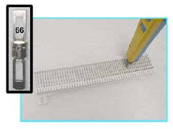
Question: What's a KT-66 Block? How do I connect to it?
Answer: The KT-66 block has been a standard "punch down" connector for telephone interconnects since 1958. It uses 200 bladed split contacts to make reliable connections on 28 gauge solid copper wire. It's one of the most common interconnects used in the telcom industry, and is often used to terminate an RJ-21x.
KT-66 blocks, AKA "66 Blocks" use a plastic snap-on frame to mount on backboards or racks. They are "indoor only" interconnects which may fail if exposed to moisture.
KT-66 blocks come in several styles. Some are "split blocks" in which the two spade terminals on each end of the block are connected together, but the connection is "split" down the center of the block. Other KT-66 blocks may have 50 pin AMP connectors on either side of the block.
To make a reliable connection to a punch down block, you'll need a "punch down tool" as pictured below. Be sure to use the correct "66" style blade to make the connection. One side of the blade will cut the wire, and the other is for "loop through" wiring.
Make sure you connect only one wire per terminal. Stacking wires on top of each other will result in unreliable connections.
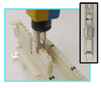
Question: What's a 110 Block? How do I connect to it?
Answer: The 110 block has been a standard "punch down" connector for telephone interconnects since 1971. It was intended to be a high density replacement for the KT-66. It uses a plastic frame to which a series of 4-pin connectors may be attached. Up to 50 of these connectors may be attached to the block. With 110 blocks, connection density is 50% higher than connections made on a 66 frame.
KT-110 blocks, AKA "110 Blocks" use a plastic snap-on frame to mount on backboards or racks. Like the "66 Block", a 110 block is "indoor only" and should not be exposed to moisture. You must use the right tool with the right blade to make a reliable connection on a 110 block as shown below. Insert only one wire in each slot.
Question: What's a 270 Block? How do I connect to it?
Answer: The 270 block is more common in Europe than the US, but chances are you'll run across them when installing loggers. Here's the tool you'll need to make a reliable connection to these blocks:
Question: What is an RJ-45 jack? Which wires connect to each pins?
Answer: Although it's not technically correct, the term "RJ-45" is now used to refer to any standard 8 pin jack in telephony or networking applications. RJ-45 jacks are most commonly used in Ethernet applications. Here are the correct wire colors for each pin in an RJ-45 jack connected to CAT-5 cable:
Pin 1 - Orange/White
Pin 2 - Orange
Pin 3 - Green/White
Pin 4 - Blue
Pin 5 - Blue/White
Pin 6 - Green
Pin 7 - Brown/White
Pin 8 - Brown
In telcom applications, eight pin jacks are used to carry four analog circuits. The most common pinouts are:
|
Jack Positions |
USOC RJ61 |
T568A |
T568B (AT&T) |
100BT (LAN) |
| 1 | wht/brn | wht/grn | wht/org | wht/blue |
| 2 | wht/grn | grn/wht | org/wht | blue/wht |
| 3 | wht/org | wht/org | wht/grn | wht/org |
| 4 | blue/wht | blue/wht | blue/wht | |
| 5 | wht/blue | wht/blue | wht/blue | |
| 6 | org/wht | org/wht | grn/wht | org/wht |
| 7 | grn/wht | wht/brn | wht/brn | |
| 8 | brn/wht | brn/wht | brn/wht |
These 8 pin jacks look identical to an RJ-48 (described below), but the wiring is different. An RJ-48 is just for T1/E1 lines.

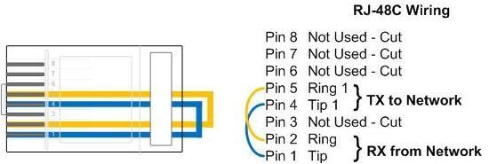
Question: What is an RJ-48 jack? What is the pinout? What is the impedance of a T1 line?
Answer: An RJ-48 jack is the standard termination for a T1 or E1 line. Here is the standard pinout:
Transmit + = Pin 1
Transmit - = Pin 2
Receive + = Pin 4
Receive - = Pin 5
Pins 3,6,7 and 8 are unused. T1 line impedance is nominally 120 ohms. If you're bridging a T1 line with a channel bank or logging card, you'll want an input impedance of at least 1K ohms on the bridging device.
Question: What is the pinout required for an RJ-48 T1 crossover cable?
Answer: Just cross connect the transmit and receive pairs as shown below:
1->4
2->5 Tx goes to Rx
4->1
5->2 Rx goes to Tx
Question: What is the pinout required for an RJ-48 T1 loopback plug?
Answer: Just loop the transmit and receive pairs as shown below:
Question: What is an LBO level on a T1 channel bank? Why would I need to adjust it?
Answer: To ensure that a T1 channel bank will work on a large variety of lines, it is adjustable over range of analog levels. LBO levels are usually set by dip switches or potentiometers within the channel bank. It's essential that these be adjusted correctly so that DTMF and caller-ID can be decoded properly. Audio fidelity is also increased when the line is properly adjusted. To adjust the level, measure the line with a TIMS set and set it to a maximum level of +0dBm.
Question: How can I make a waterproof telephone wiring connection?
Answer: There are several types of waterproof connectors used in phone wiring. The three most common types are:
EX Connectors or "Jelly Filled Beanies"
Use these where you have exposed leads or corroded wires. Beanies cut through and displace the insulation on up to 3 conductors. Beanies take longer to crimp than the Scotchflex connectors below, but they have a larger contact surface area. These are filled with a waterproof gel and work well on a wide range of conductor sizes, from 18 to 30AWG.
UR and UY Connectors
Made by Scotchflex, these connectors are quick to install. The UR is a butt-splice type connector, and the UY is an inline connector. Use pliers for a good crimp, and make sure the red button ends up level with the body of the connector. If it is tilted, it won't make a good connection. Scotchflex connectors work on wire sizes from 19 to 28 AWG.
There are also larger connectors, such as BPTS splices which are can handle up to 200 conductors.
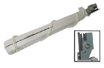
Question: What is the minimum equipment I'll need to install a logger? What is a "butt-set"? What is a "hound"? What is a "toner"? What is a TIMS?
Answer: In addition to the correct connection tool (probably one pictured above), you'll need a way of checking what's on a line to properly install a logger. There are two devices which will help. One is a "butt set".
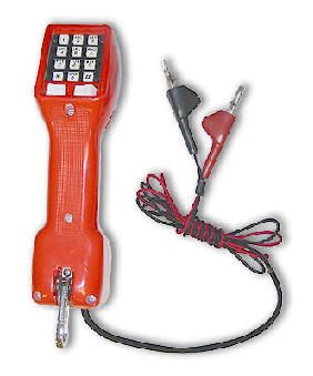 A "butt set" is essentially a portable telephone which will allow
you to test analog wet or dry lines. It has a switch marked "M"
which will capacitively
couple the set to the line. Use the "M" mode to monitor
the line in high impedance, and switch to "D" to put the set in 600
ohm mode. The green LED will illuminate if the line polarity is correct
(black to ring, red to tip). If line polarity is reversed, a red LED will
illuminate.
A "butt set" is essentially a portable telephone which will allow
you to test analog wet or dry lines. It has a switch marked "M"
which will capacitively
couple the set to the line. Use the "M" mode to monitor
the line in high impedance, and switch to "D" to put the set in 600
ohm mode. The green LED will illuminate if the line polarity is correct
(black to ring, red to tip). If line polarity is reversed, a red LED will
illuminate.
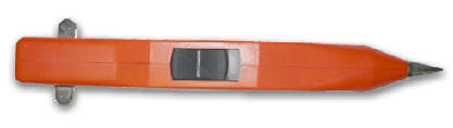
Another handy tool that will take the place of a butt-set is a "hound". A hound is nothing more than an inductively coupled amplifier with a small speaker in a hand-held tool. Use it to monitor the audio on the line and verify you have the right pair before connecting it. Since it won't load the line, you'll be able to monitor on-hook noise also.

Another handy tool is a "toner". This is essentially a signal
injector without level controls. Most toners send either a warbling tone
at +14 dBm or a constant tone at about +6 dBm.
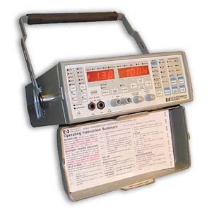 To really
do the job right, you'll want a TIMS set. TIMS stands for Transmission
Impairment Measurement Set. A TIMS is a combination of a calibrated signal
injector with a calibrated meter. It can be adjusted to match line impedance
and can measure noise levels on the line. A TIMS will help you install
loggers by verifying the incoming line levels and checking the quality of your
wiring. DLI carries affordable used and new TIMS.
To really
do the job right, you'll want a TIMS set. TIMS stands for Transmission
Impairment Measurement Set. A TIMS is a combination of a calibrated signal
injector with a calibrated meter. It can be adjusted to match line impedance
and can measure noise levels on the line. A TIMS will help you install
loggers by verifying the incoming line levels and checking the quality of your
wiring. DLI carries affordable used and new TIMS.
Question: How can I adjust the VOX timeout?
Answer: Our larger loggers use a program called “LoggerConfig” to modify the values stored in a configuration file named “Logger.INI”. Use this editor to modify your line settings including line names and VOX timeouts. To start the editor, click on Start->Programs->Digital Loggers->LoggerConfig.
Our CD loggers and 4 channel network loggers have a separate VOX timeout parameter for each line in the setup menu.
A typical timeout value for radio calls is 10 seconds, and 30 seconds is commonly used for phone calls.
Question: How can I inject a "record tone" or "warning tone" into the handset of a phone being recorded?
Answer: There are two ways to do this:
One is with a small logger patch which connects externally to the handset connector. A typical unit is the Dynametrix patch Make sure you order the correct patch for your type of phone. Since there are several types of microphones, (dynamic, electret condenser, and carbon), there are several different patches available. Also, you may need an adapter cable if you have a Sony or Panasonic phone system which does not use standard handset wiring. External logger patches typically cost $100 per set.
To reduce the clutter on the desktop, there's a second, more expensive option. Send your phone set in to a dealer, and they can install the record tone inside the set. This is commonly done on Avaya station sets in telemarketing applications. Plan on spending $150 to $200 per set if you choose this option.
If you are connecting a logger to an outside analog line or to a port on the PBX, you can inject the tone directly into the port or trunk, so you won't need a logger patch.
Question: How can I adjust the VOX sensitivity on my 24 channel logger?
Answer: The sensitivity is automatically adjusted using a noise-canceling VOX IC from Motorola. If the input level is well over 0dBm, you may need to add a series resistor to increase sensitivity and eliminate clipping. A 27K ohm resistor will shave off about 5dBm.
Question: How many recordings can I store on disk? Can I compress evidence recordings?
Answer: That depends on the length of each recording, and the sampling rate. Higher sampling rates equate to higher sound quality, but use more disk space. Lower sampling rates are called “compression”, and they sacrifice audio quality in exchange for smaller files. Defense attorneys have argued that modifying recordings using audio compression amounts to “tampering” with the original recording. If you have the choice, record all lines in full fidelity. All DLI loggers are capable of uncompressed recording on all channels simultaneously. They are also capable of compressing audio on all channels simultaneously. This allows you to keep a legal, full quality copy of each recording. If the recording is not accessed, it can be automatically compressed to conserve disk space. u-law recorded files take up about 1MB for each 2 minutes of recording. That equates to 2,000 minutes (or about 33 hours) per gigabyte of disk space. A 650MB CD holds about 21 hours of recording in u-law format.
Question: How can I eliminate radio interference in the recordings?
Answer: First, make sure you logger and phone equipment is properly grounded. If the problem persists, you can attenuate the overall level going into your logger, or you can add a separate external RFI (Radio Frequency Interference) filter to the unit. To attenuate the line, add a series resistor (ie. 20K) to reduce the level going into the logger. Confirm the level with a TIMS set.
Question: How do I connect a microphone?
Answer: Your microphone should be connected through a preamplifier that brings the output level of the microphone up to an acceptable level (approximately 0dBm peak). DLI Microphones are self-powered and include an internal preamplifier. They are connected using a 6 pin RJ-12 cable. Power to the microphone is provided on pins 1 and 6 of the connector. The red LED on the back of the logger indicates that the logger is providing power on these outermost pins. If these connections are shorted, the LED will extinguish without damage to the logger. An automatic circuit breaker will restore power after wiring is corrected.
Question: How do I cable a microphone?
Answer: If you are using a DLI microphone with a higher level output (0dBM Peak), you can use standard unshielded twisted-pair telephone cable. DO NOT attempt to run multiple microphones through a single CAT-5 cable. The crosstalk may be unacceptable. If you are using lower level microphone sources, you must use shielded twisted pair cable to eliminate noise and crosstalk. Don't use twisted pair cables for low-level microphones, particularly when the cables will be located near fluorescent lights. Be sure to connect the shielding braid at the microphone end of the cable and avoid ground loops.
Question: What is a "Speech Path Connection"? What is a "port"? What is a "channel"?
Answer: A speech path connection is an electrical path inside a phone switch which allows communications between two or more stations. In logging, each speech path typically requires a logging port. A channel is the same as a port. Each port on a logger is separate input source for a speech path. The number of channels you require depends on the number of conversations you need to record simultaneously. You can reduce the number of channels required by switching a smaller number of logger ports to a larger number of speech path connections through a switch, multiplexer, or PBX.
Question: What is a Decibel? What is a dB?
Answer: Telecommunications line levels are measured in decibels (dB). Decibels are a power ratio measurement. Voltage, sound intensity, and electrical power may be expressed in decibels. Telecommunications levels are typically expressed as a ratio of power in either dBm or dBv. The most common measurement is the dBm, which refers to a decibel level measured with respect to a one milliwatt signal (typically on a 600 ohm line). Zero dBm is defined as a reference level of one milliwatt of power into 600 ohms. A change of three decibels is approximately double the power. A change of 60 decibels refers to a power ratio of 1,000,000 to 1. Typical phone line levels are –3dBm peak for bridging outside lines, and –13dBm for bridging handsets. DLI Loggers will operate reliably with peak input levels in the range of –40dBm to +3dBm. Higher levels need to be attenuated, and lower levels need to be amplified prior to connection to the logger. A transmission impairment measurement (TIMS) set or true RMS voltmeter with differential input is useful for checking input levels prior to installation, and for troubleshooting logger connections. Click to read more on how decibels are used in measuring audio levels and to brush up on what a logarithm is.
Question: What is a Noise Floor?
Answer: Phone line noise floors may range between –84dBm for a very quiet line to –35dBm for a noisy line. Noise is typically worst on wet lines when all phones are on-hook and the line is unterminated. Local telephone companies have noise specifications based on the line distance to the central office. Noise may be measured using a TIMS, and line distance is measured using a time domain reflectometer (TDR). The VOX circuitry in DLI network loggers automatically compensates for varying noise floors. Additional circuitry in these loggers eliminates on-hook noise when wet lines are detected. Noise floors can be significantly increased when analog pairs are located near digital pairs. An example would be a long run handset back-haul from a digital phone. If noise floors exceed acceptable levels, a separate cable with a tighter wire twist should be considered. In the real world, this translates into the use of CAT-5 or CAT-6 quality cables when lines are run near transformers or fluorescent lights, or over long distances.
Question: What is Line Impedance?
Answer: Impedance is a measure of AC resistance. Lower resistances require higher currents to achieve the same voltages. Telephone lines are terminated and matched to their “characteristic impedance”. A “characteristic impedance” is the most efficient way to transmit power through that particular type of wire. Most phone lines are 600 Ohm impedance, although 135 and 120 ohm lines are also common.
To achieve efficient transfer of energy over a transmission line, the impedances of both the sending and receiving equipment must be matched. If this is not done correctly, transmission loss will occur. The total impedance present on a phone line at a customer site is typically 900 ohms. All DLI loggers will directly connect to lines in this impedance range, as well as to high impedance sources, such as handsets.
Question: What is the impedance of a Headset or Handset?
Answer: Most headset and handset impedances are in the range of 600 Ohm to 10K Ohm. These connections may be directly bridged using a “Y” connector, which ties to the logger. In call center applications, the connection to the headset may be made inside the telephone itself, and the audio may be back-hauled through an unused pair on the cable, or through a separate recording cable.
Question: What is a "recording supervisory tone"? How can I inject this into the line?
Answer: This is a feature used to remind callers that they are being recorded. It consists of a 1500Hz beep tone injected on the line at -6dBm for 500ms every 15 seconds. If you are using one of our 4 channel loggers, such as the government model CD logger or 4 channel network logger, a tone generator is built into the unit. To use this feature, you'll need to be connected to an outside analog trunk line. This recording tone feature is not provided on our USB logger, 24 channel logger, or on the Personal Logger.
If you're connected to a handset, you won't be able to inject the tone through the earpiece. Recording tones need to be injected through the microphone pins or through an outside trunk. Products for microphone tone injection are available from Dynametric.
Consider using a voice-mail system as a better way of informing callers that they are being recorded. Using a PBX, a separate hunt group can be established to announce "Your call may be monitored and recorded for quality assurance purposes...".
Question: How can I connect a Motorola radio to my logger?
Answer: RJ-45 connectors are common on Motorola. The exact connector and pinout depends on your radio model. For information on Motorola pinouts, click here.
Question: How can I record in VOX mode when a supervisory tone is present from an external source?
Answer: You have two options. You can run the line in contact closure mode if you have a dry contact recording control output from your console. Or, you can set the radio to disable the supervisory tone so it doesn't trop the VOX. You can also filter out the tone (It's typically 2700Hz), but audio quality will be significantly degraded, so we don't recommend that.
Question: What is the impedance of a Radio output?
Answer: Most radio audio sources intended for connection to speakers are very low impedance (typically 4 to 8 ohms). If you are connecting to a radio receiver output that is intended for a speaker, bridge the line directly at the speaker connection. If you choose to disconnect the speaker, a load resistor placed across the line may be necessary for the radio amplifier to function properly.
In an E-911 application, the console will typically have a recording output which is a 600 ohm balanced line.
If the output level at the bridging point is over +3dBm, you should add a series resistor to bring it within the logger’s input range of -40 to +3dBm. An example of a high level audio source is a 70-volt public address speaker system. Connecting a 470K ohm resistor in series with a 70-volt system will bring levels within the recording range of the logger. A transformer may also help to match impedance if the logger is located a long distance from the radios.
Keep in mind that the input impedance of the logger is over 10K ohm. The logger is “AC coupled”, and “DC Blocked” with capacitors at the input stage, so you cannot measure the logger impedance directly with a DC meter.
Question: What is a Wet Line? How can I tell if I have a Wet line?
Answer: Wet lines are phone lines that draw power from the central office, or from a PBX. Audio is superimposed upon the DC power. Power to the station set is direct current (DC), and is typically 48 volts. To determine if you have a wet line, you can connect a DC voltmeter across the line. A typical voltage range for a 48-volt wet line in on-hook state is 44-50VDC. A typical voltage range for a 48-volt wet line in the off-hook state is 5-15VDC when measured across the equipment seizing the line. The MIL-4000N may be connected directly to either wet or dry lines due to the DC blocking within the logger.
Question: What is “On Hook Noise”?
Answer: On Hook Noise is the noise present on a telephone communications line when the phone is not in use. The MIL-4000N includes circuitry designed to eliminate on-hook noise on 48-volt wet lines. This minimizes noise input to the VOX circuitry. Line voltages over 41VDC cause the logger to reduce input sensitivity, minimizing false VOX trips when the line is on hook. An additional circuit will detect rings, start recording, and allow caller-ID to pass to the recording. This on-hook control feature is automatically disabled when the logger is connected to a dry line. Larger loggers use external line voltage mute boards.
Question: What is a “Loop Start Line”? How can I tell if I have a loop start line? How do I connect a loop start controller?
Answer: Loop start lines are phone lines which use a loop current to control on-hook or off-hook conditions. Your home phone line is probably a wet loop start line. To determine if you have a loop-start line, you can call the phone company, check the tag at the demark point, or use a meter to check the line. Loop start lines can also carry signaling information when the phone is on-hook. A common example is a CENTREX line with COV signaling. To log the audio only (and avoid recording the signaling), you'll need a Loop Start Interface Card.
A loop start controller is a unit which disconnects the phone line from the recording equipment when the customer equipment is not in use (on-hook). It does this by sensing the line current on the loop-start line. A current between 8 and 80 milliamperes indicates an active loop.
To install a loop start controller, you'll need to make three connections. The first two go to the outside line (CO), and to the customer equipment (CPE). The controller will monitor the current between these two connections and activate the third port only when the customer equipment goes off-hook. Connect the third port to your logging device and you're done.
Question: What is a “Wink Start Line"? How can I tell if I have one?
Answer: Not to be confused with loop-start, wink start signaling is commonly used on DID lines. On a wink start line, the CPE or PBX first seizes the line by going off-hook. Before connecting the call, the CPE waits for an acknowledgement from the other end. The acknowledgement is a reverse of line polarity (off hook) for a duration of 140 to 290ms. This is called a "wink". The wink serves as an integrity check and can be used to identify a malfunctioning trunk. If the CPE detects a malfunctioning trunk, it may switch to another line. Just use a voltmeter connected across the line to tell if you have a wink-start line. You'll notice the polarity reversal when the line is picked up (seized). If you're using a "butt-set", the red and green LEDs will flash alternately when the line is seized.
Question: What is an “Immediate Start Line"? How can I tell if I have one?
Answer: An immediate start line uses no line seizure handshaking. The originating side (CPE or PBX) seizes the line by going off-hook, and just starts sending digits without checking the line condition or waiting for a response. You'll know you have an immediate start line if the CPE goes off-hook and dials with no outside connection.
Question: What is a "Wet Delay Dial Line"?
Answer: In Delay Dial mode, the originating side (CPE or PBX) seizes the line and then waits for 150 to 150ms. After that, it checks to see if the line is on-hook (with normal battery voltage). If so, it will dial digits. If not, it waits until the line goes to normal polarity and then dials. You can determine if you have a wet delay dial line by watching the polarity LEDs on a butt-set.
Question: What is a “Ground Start Line"?
Answer: Ground start lines are seized when the originating side briefly connects the ring side of the line to earth ground. Ground start lines are used to connect most pay phones. The most common use of loggers with ground start is in correctional facilities which monitor inmate pay phones.
Question: What is a “COV Line"? What is Code Over Voice?
Answer: COV stands for "Code Over Voice". COV signaling is used mainly on older voicemail systems to aid in communication between the voicemail system and a separate PBX. COV signaling uses high frequencies above the voice band to send signaling data. These high frequencies are superimposed on the audio signal and then filtered to separate them from the voice signal when recording.
Question: What is bandwidth? What is the audio voice band? What frequencies are sent over a phone line?
Answer: Telephones have a frequency response curve tailored to transmit audio between 300Hz and 3.5KHz. This is the spectral area in which most of the energy is present in the human voice. Accordingly, most phone connections have a bandwidth of approximately 3Khz. Most analog phone equipment has a 3dB per octave roll past these frequencies.
Question: What is a “Dry Line”?
Answer: Dry lines are phone lines, which transmit audio, but not power. Dry lines measure 0VDC at all times when checked with a DC voltmeter. Dry lines may be connected directly to the logger. To connect a dry line, first verify that it is within the levels mentioned above, then bridge it directly to the logger input. Dry lines do not require a loop start interface card or line voltage interface card. Connect dry lines directly to your DLI logger.
Question: What is a “Balanced Line”? What is an “Unbalanced Line”? How can I connect to them?
Answer: Balanced lines are lines use to cancel noise. In balanced phone lines, two wires are twisted together so that each wire picks up the same amount of noise. At the receiving end, the noise is subtracted, and the resulting output is the sent audio, minus the noise. A balanced line becomes "unbalanced" when unintentional leakage to ground occurs. Unbalancing a phone line causes noise. This can be a result of poor insulation somewhere along the line, or a bad connection. The problem is often worse in the winter, when outside lines are wet and leakage to ground occurs along the line.
Audio is usually sent down shorter unbalanced lines using Coaxial shielding. This shielding prevents electromagnetic noise from affecting a single wire. The inputs to all DLI loggers are balanced lines. These inputs may be connected directly to unbalanced (i.e. Coaxial) lines, and the ground may be connected to either side of the logger input.
Question: What is a “Capacitive Coupling”?
Answer: Capacitive coupling refers to the type of circuitry used in DLI loggers to connect to an outside line. This type of coupling draws no DC current from the phone line, so there is absolutely no DC loading (no DC current flows through the logger) when connected to wet lines.
Question: What is a POTS line?
Answer: POTs is a generic acronym for Plain Old Telephone System. POTS lines may be wet lines or dry lines, and may use a variety of signaling formats, such as ground start or loop start. The one thing all POTS lines have in common is that they are balanced analog lines, typically with a 600 ohm impedance.
Question: What is a “2 Wire” line?
Answer: A two wire line uses a single pair of balanced conductors to carry both the transmitted and received audio paths. The most common "POTS" or Plain Old Telephone System lines are 2-wire lines. Better audio quality and separation is achieved when using 4 wire lines. A hybrid can be used to convert from 2-wire to 4-wire line configurations.
Question: What is a “4 Wire” or “E&M” Line? How do I connect to it?
Answer: Four wire lines employ a separate path for both heard (ear) and spoken (mouth) audio. These lines are also called E&M or Ear and Mouth lines. You can think of each line as a pair of two wire lines, each going an opposite direction. An external transformer combiner (hybrid) is required to convert a four-wire E&M system into a two-wire output for the logger. Four wire E&M lines should not be confused with single-pair lines in which a four-wire cable is used, but only the center pair carries audio.
Question: What is a D/A Converter? How do I connect it?
Answer: D/A stands for Digital-to-Analog. A D/A converter is installed between digital lines (usually station sets) and an audio logger. D/A converters work by converting the signal stream from a digital station set into the standard analog format used in an audio logger. They are available in single and multi-channel versions.
Since there is no "standard" for digital station set interconnects and line formats, single channel D/A converters are usually best purchased from the manufacturer of the PBX and station sets to which you are connecting.
Multi-channel D/A converters are commonly available on PCI cards. Another common type is built into the base of a KT-66 punchdown block. Again, every phone system has a different format, so there are hundreds of D/A converters available. Make sure you are purchasing the right one for your PBX and station sets.
Question: What's a DSL line? How do I connect to a logger to record the analog audio on a Digital Subscriber Line (DSL)? What types of DSL lines are there and what's the difference? What do all these acronyms mean?
Answer: DSL stands for Digital Subscriber Line. DSL refers to a technology used by the phone company to increase the amount of communications (data or audio) that can be passed down a single pair of copper wires for short distances. Getting more out of an existing phone wire is referred to "increasing copper bandwidth" or "pair gain". By transferring data faster, the existing (and expensive to replace) telephone infrastructure is able to handle more call traffic. DSL increases the amount of data sent on an analog pair by sending much more than the 64Kbps required for a single analog line down the same copper pairs used by analog lines.
Some types of DSL lines are "hybrid", and carry both digital and analog data simultaneously. When things are working perfectly, there should be no interference between the two signals: digital data and analog voice. In the real world, filtering is sometimes needed to prevent the digital subharmonics from entering the analog channel.
While DSL is usually as fast or faster than a T1, it is not necessarily as reliable. Phone companies try to counter this downside by offering refunds and "service level agreements" for DSL lines.
Although it's somewhat beyond the scope of this logging FAQ, here's a quick explanation of the various types of DSL lines.
G.Lite is also called "DSL Lite", "Universal DSL" or "splitterless ADSL". G Lite is a slower version of ADSL that USUALLY requires no splitters or filters. G.lite uses a "fast retrain" technique to negate the various signal disturbances caused by normal POTS usage. Currently G.Lite supports speeds up to 1.5 Mbps/512 Kbps.
SDSL is "Symmetric Digital Subscriber Loop" indeed symmetric with a maximum rate of 1.5 Mbps/1.5 Mbps. SDSL requires a dedicated line. You won't be attaching an analog logger to an SDSL line, as they are only for digital data.
ISDN-DSL is "ISDN Digital Subscriber Loop." At 144 Kbps/144 Kbps, this is really a custom ISDN variant designed by Lucent. It uses the same 2B1Q data encoding as ISDN. IDSL does require a dedicated line however and does not support a concurrent POTS line, so you can't attach an analog data to an IDSL line unless you use an IDAC.
RADSL is "Rate Adaptive Digital Subscriber Loop". Developed by Westell, RADSL runs at 2.2 Mbps downstream and 1.0 Mbps upstream. RADSL adapts by changing speed in response to line conditions. Like ADSL, RADSL can piggyback on the POTS line. RADSL providers will tell you that no filters are needed, but don't trust them. Most installations do require a filter in our experience.
HDSL is "High bit-rate DSL" and is the original versions of DSL. HDSL requires multiple, dedicated wire pairs, and is symmetric at 1.5 Mbps/1.5 Mbps (the speed actually depends on number of wire pairs used). HDSL cannot piggyback a POTS line, so there is no analog transmission capability.
VDSL is "Very high rate Digital Subscriber Loop". VDSL still in development with downstream capacity of 52.8 Mbps, and upstream of 2.3 Mbps. VDSL may work on copper connections up to 80 meters, but is really designed for fiber optic technology.
UDSL is "Unidirectional Digital Subscriber Loop", a proposed new standard from Europe that is not yet available.
Question: What's a DSL line filter and why do I need one?
Answer: A logger may be connected to DSL lines which support concurrent POTS operation by inserting an analog filter between the line and the logger. When connected in this manner, the logger will record the ANALOG data on the line, not the superimposed digital data stream. These filters are usually provided by your local carrier when the ISDN line is installed. The most common filter is the simple "PI" filter pictured below:
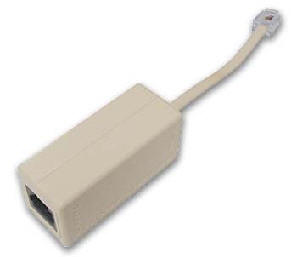
It usually provides about a 20dBm improvement in separation. For particularly noisy lines, you'll need a filter like this:
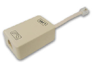
These Malmax filters give an improvement of approximately 38dBm.
Purchased a network
logger from DLI? Need filters? Call us (408) 330-5599.
Question: What's ISDN? What's B-ISDN? What's an ISDN line? How do I connect a logger to record from an ISDN line?
Answer: ISDN stands for Integrated Services Digital Network. It's really a complete design for a high-speed telecommunications network. It was originally designed to carry voice and data at high speeds over copper, fiber optic, and microwave connections. ISDN is still being installed in many US locations, but most experts agree that it will eventually be replaced by DSL for applications of 3 miles or less. However, in some locations where the physical wire lengths from the office are over 3-4 miles, ISDN may be more practical than DSL.
B-ISDN is "Broadband" ISDN. (Original ISDN is often called Narrowband ISDN.) B-ISDN is a complete redesign of ISDN to provide higher bandwidths on both long and short line connections.
To connect a logger to an ISDN line, you'll need to use an ISDN to POTS converter. They're manufactured by companies like ADAK, AT&T, ELSA and KNX. These converters provide a bridge between the ISDN digital format and the more common analog format used in logging recorders. These are also commonly called iDACs.
ISDN is also often used in PBX's and Centrex installations as a communications format between the PBX or CO and the station sets. A passive tap is required to bridge from the ISDN connection in these applications. Learn more about ISDN here.
Answer: Centrex is a generic marketing term used by phone companies to describe a Central Office (CO) switching system. With Centrex programming installed at a CO, the customer can have business class phone services like call forwarding, caller ID, caller ID blocking, call return, conferencing and call waiting. A Centrex installation uses the phone company switch to handle these services, so there is no Private Branch Exchange (PBX) or Key Telephone System (KSU) located at the customer site. This saves money on the initial installation. The phone company then provides a separate line for each extension, and handles the switching features inside the CO. Centrex installations are usually made in smaller companies with 50 extensions or less. Centrex may be installed using ISDN, DSL, or POTS lines.
Since "Centrex" is a business term, a brief explanation of the business aspect is in order. A "Centrex equipped" line will cost more per month than an ordinary line. One advantage of installing Centrex is that the up-front cost of a PBX or KSU is avoided. Another advantage is that the phone company will usually provide programming services at minimal cost. Two disadvantages of Centrex are that more lines need to be installed (one per extension as opposed to one per voice-path), and that monthly costs may be significantly higher.
On-hook signaling is typical on Centrex lines. To connect a logger to a Centrex line, first determine what type of line you have at the station sets. The most common line for a Centrex installation is probably a loop-start POTS line, which can be directly connected to an analog logger.
Another common Centrex line is "National ISDN-1 2B+D". This line uses up to two bearer channels (B Channels), each with a 64K bandwidth, adequate for one u-law channel. This line also contains a signaling channel, called the "D Channel", which transfers data at 16Kbps. At the customer site, this line is connected to a network termination unit called an "NT-1". Analog phones and loggers can then be connected to the termination unit. Several types of adapters are available to terminate an ISDN line, depending on the type of equipment you want to attach. These acronyms describe the adapters and equipment required to connect to ISDN lines:
- NT1 - The network termination unit that connects the ISDN circuit at your site. Typically built into the terminal adapter or the router.
- NT2 - A network termination unit that connects multiple users (or devices) onto one interface. This device is typically a PBX or a multiplexer.
- TE1 - This term refers to full-digital ISDN compatible terminal equipment, such as an ISDN telephone set.
- TE2 - This term refers to equipment which is not directly compatible with ISDN, such as standard analog telephone sets, audio loggers, personal computers, FAX machines or modems. All TE2 type equipment requires a TA (below).
- TA - A terminal adapter allows non-ISDN-compatible equipment (TE2) to be connected to an ISDN circuit.
ISDN circuits require an independent power source, typically built into the terminal adapter or the router.
Centrex services are media-independent, meaning that the switching features can be provided regardless of the line type. For example, a DSL line can be equipped with Centrex as easily as a POTs line.
Question: What a "hybrid"? What is transmission loss? What is a "duplexer"? How do I adjust it?
Answer: When a signal is sent down a transmission line, it is received at a lower level than it was transmitted at. This loss of signal is referred to as "transmission loss". A hybrid or "duplexer" is used to compensate for the transmission loss that occurs on a transmission line. The most common duplexer you'll encounter is used on a 2-wire balanced analog line.
Question: What is a T1 line? How does it work? How do I connect to a T-1 Line (DS1 Line)?
Answer: The Bell System designed the T1 carrier communications system in the early 1960s to handle interoffice communications between COs. A T1 line is a digital phone trunk which carries up to 24 channels of u-law data at 64Kbps for an aggregate rate of 1.544Mbps.
A T1 line can carry audio, data, or a mixture of both. A T1 line is purely digital, unlike the hybrid DSL lines described here. In general, T1 lines are much more reliable than DSL lines. T1s function well over distances from 15Km to 65Km on ordinary copper pairs.
T1 lines work by time division multiplexing 24 voice channels into time slots in a round-robin manner. Each voice signal is first sampled at a rate of 8000 samples per second in the standard u-law format. This format is identical to the recording format used in all DLI logging products. The least significant bit of each sample is periodically (usually once each 6 samples) used to send signaling information. This signaling information includes the information necessary to set up the call, start or stop the call, detect errors, and handle billing. Each of the 24 channels is then interleaved in a specific method of combining which was designed to use the existing multiplex equipment available in early phone switching facilities. A set of 24 eight-bit samples (one from each channel) form what is called a "frame". Each frame occupies a time period of 125usec. A single bit is inserted after each 192 (24x8) bit frame to synchronize the data and prevent "channel skip". This makes a total of 193 bits sent 8,000 times a second, or 1.544Mbps.
T1's are normally installed as 4-wire lines (Ear and Mouth configuration). Recently, some COs have started installing DSL bridges to cut the wiring involved down to a single pair. These bridges typically are installed at the demark point in the customer facility and are usually used only when the customer is less than 15,000 wire feet from the CO.
To connect a logger to a T1 line, your best bet is usually a channel bank. They are flexible, inexpensive, and easy to install. You can also use an Intel (formerly Dialogic) board, but a channel bank usually works better in the long run. New channel banks are available in 1-U high 19" rack mount or wall mount configurations. One important thing to watch for when using a channel bank is the analog line level. Channel banks use switches called LBO's to adjust the analog line levels. Most channel banks provide separate receive and transmit adjustments. These adjustments must be set correctly, or problems decoding caller-ID and DTMF touchtones in recordings may occur. Getting these settings right will also keep the echo cancellation on the line working properly. To set these levels, use a TIMS set.
Question: What is a "Contact Closure Input"?
Answer: Contact closure inputs are common on radio dispatch consoles, 911 systems, and courtroom recorders. They provide a positive start/stop signal which is more reliable than VOX recording. By using a contact closure to start and stop recording, recording will continue if the phone is off-hook, even if there is no audio on the line. This is often the case when a 911 caller leaves the phone for a few minutes. To use the contact closure output of a console, you connect the normally-open relay output of the console to the logger. One wire switches the channel you are recording on, and the other wire is a common ground connection. This type of circuit is called a "dry contact", because the contact does not control any appreciable amount of power, and there is no DC sent from the console to the logger. When the relay contact closes, recording starts. When it opens, recording stops and the file is closed. Contact closure control of recording also prevents the supervisory tone which is commonly found in radio systems from triggering the VOX operation of the logger. In some situations, such as a jail cell, or interview room, a switch may be placed on the outside of the room to control the start and stop of recording from a microphone within the room. In courtroom applications, a stenographer's foot pedal may be connected to control recording. A "normally open" microswitch is used in the foot pedal. If you need a contact closure input on either any network or CD logger, please specify the number of channels required when ordering and we'll add the hardware to your quote.
Question: How can I select an Uninterruptible Power Supply (UPS) for my logger or phone system? How can I convert from Amps to Watts and from Watts to BTUs?
Answer: First, check the total power requirement. Power is measured in watts. A watt (power) is equal to one volt (voltage) multiplied by one ampere (current). You can either measure the power your system draws with a wattmeter, or you can check the documentation. A UPS is rated in two ways. The first rating is the maximum wattage. This is the maximum amount of power you can draw from the UPS. The second rating is the energy capacity of the UPS. This is typically in jewels, where one jewel (J) equals one watt for one second. There are 3600 seconds in an hour, so 3.6KJ = 1 watt for an hour, and 3.6MJ=100 watts for an hour. This determines the amount of time that the UPS can supply power at a given rating. This "run time" is governed mainly by the size of the batteries in the UPS. Many UPS systems have an external battery connector that can be used to extend run time. These are the approximate average power consumptions of DLI loggers by part number: MIL-4000C/G= 45 watts, MIL-4000N=31 watts, MIL-8000U=9 watts, MIL-2400 system with disk array= 680 watts, MIL-4800 with dual disk arrays = 810 watts. Using these numbers, a 100 watt 3.6MJ UPS will run a MIL-4000N comfortably for over 3 hours. We recommend a UPS which can handle twice the average power consumption. This helps handle the surge of power that is required when disk drives and power supplies initially start up. To convert to British Thermal Units (BTUs) per hour, multiply watts by 3.41

If we haven't answered your questions here, please call (408) 330-5599 or send us an email. We'll be glad to help.
This page copyright Digital Loggers, Inc. 2001-2018. Trademarks are property of their respective holders.