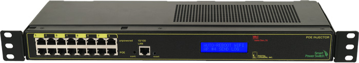
POE Injector FAQs
Find the Gig-E manual here. What accessories are available?
Call now (408) 330-5599.
Frequently Asked Questions
What are the DC power, current and voltage
ratings?
What's new in the product?
How much voltage loss can I expect in an Ethernet cable?
How can I connect
external batteries?
What will / won't the product do?
Are you building a Gig-E variant?
Does it support reverse polarity?
Why is the loud alarm sounding?
How can I destroy the product?
How do I set up
network access from Windows?
How do I set up
network access from an Apple Macintosh? - Thanks to John McClintock
How do I set
up Internet access from a home router? -Thanks to Mike G.
What is the current firmware version?
How do I enable AutoPing?
How do I use Wake on Lan?
What's the PoE pinout?
What's the ground stud for?
How do I jumper the battery charger?
What components do I need to build a remote DC powered site?
What is the 24V model "cut out" voltage?
How can I tell if a PoE cable is
shorted or a device is wired in reverse polarity?
What's the Scripting Language all about?
What's syslog? How can I keep an event log?
What is the default IP address?
How do I reset to defaults?
What is the default password?
On initial setup, I can't establish a Ethernet communications from a Windows PC. Help!
Do I need a crossover
cable?
How can I control the switch from my own applications?
How can I send HTTP requests?
How can I connect to Google Assistant or Google Home?
How can I connect via IFTTT?
Can you develop custom firmware for my application?
Can you develop custom hardware for my application?
What are the AC current and voltage ratings?
What is the power consumption?
Do you support PowerMan?
Can you explain the auto-ping settings?
What are the CRITICAL and PROTECT functions?
Do you have a Visual Basic.NET
example program? Thanks to Alan Holmes
Do you have a Python programming example?
Do you have a
C++ programming example?
Do you have a
.NET programming example?
Do you have a
Java programming example?
Do you have a
compiled Windows command line
tool or a Perl example?
Do you have a Crestron control module?
Where can I find iPhone, iPad,
or Android apps?
| Question: | What are the current and voltage ratings? | ||||||||||||||||||||||||||||||||||||
| Answer: |
|
||||||||||||||||||||||||||||||||||||
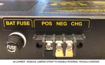
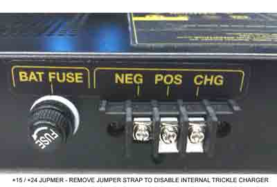
| Question: | How do I connect the charging jumper? |
| Answer: |
A battery trickle charger is included in the injector. It
is connected by default at the factory using a bridging clip on
the back of the injector. Since we've already set it up, and since it won't interfere with an external charger, no changes should be needed.. For POSITIVE GROUND systems (ie -48V) For NEGATIVE GROUND systems (ie 15V or 24V PoE, ie UBNT
Passive 24V) The CHG terminal connects to the NEG battery terminal. The POS battery terminal is bonded to ground internally. |
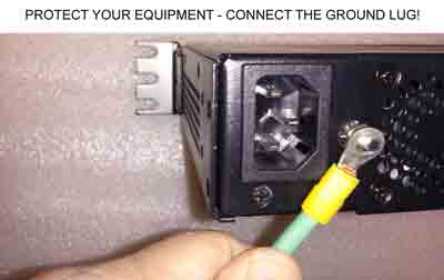
| Question: | What's the ground stud for? |
| Answer: |
This is an important connection point. It protects
both your attached equipment and the injector itself from ESD
and surges. Connect it to the best local ground point, ie.
electrical panel, telecom ground bus, ground rod, tower frame,
etc. 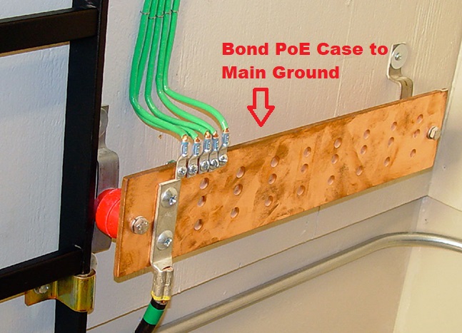 High currents may pass through this point, so heavier ie, 10AWG cable or thicker is appropriate. Leaving this unconnected will give you only the chassis ground and the 3-wire AC plug ground, which are high impedance paths. Put simply, if you don't connect the ground lug, you won't have full ESD protection. Leaving this off may also induce noise on your Ethernet cable. Do it right...
|
| Question: | How much voltage loss can I expect in Ethernet cable? |
| Answer: | Here's a handy online calculator. |
| Question: | Why is the loud alarm sounding? |
| Answer: |
A potentially dangerous over-current condition has been
detected. Disconnect the cable immediately. Check and correct
wiring. Common causes include:
If you detect any heating in any Ethernet cable, disconnect it. That's a potential hazard. |
| Question: | What's new in the product? |
| Answer: |
In July, 2018 we released the 4-port gigabit injector with 8-wire POE, separate control relays and an environmental probe.
In May, 2016 we redesigned the 24V regulator board to include a separate isolated regulator for every port. The regulation is now completely independent on each device. This makes it virtually impossible for noise, surges, or overloads on one port to affect the other ports.
In 2015, we reached the 10,000 unit milestone and made a number of firmware improvements. We are now working on gigabit versions for AirFiber and similar applications Thanks for your support!.
In 2014, we revised the PCB and surge suppression to handle high current ESD. We also selected a new fan vendor for longer-life and quieter operation.
In 2013, we added:
The product was launched in 2012, and we received a lot of great feedback from WISPs. In 2012 we added:
Firmware improvements are ongoing. Find a full list here. |
Question: How
can I destroy the product?
- Dunk it in water. This is an indoor product, exposure to weather will kill it. No warranty on that. Please no warranty claims for old "Tough Cable".
- Lightning strikes. We have at least 10 different surge protection circuits inside. Even with all that, a near or direct lightning strike will kill it... out of warranty.
- Connect the battery backwards. Won't hurt it at all. We thought of that.
- Overheat it. Nope. Thought of that too. Unit will automatically reset itself when things cool down.
- Over-voltage on the battery input. Typically, you'll just blow the fuse. Replace it with 8A fast-blow on the 24V units, 4A on the -48. You'll be up and running. Need fuses? Email us, we'll send them gratis.
- Short circuits on the output terminals. Just sounds an audio alarm. Remove the RJ-45 cable, fix the wiring, and plug it back in. In about a minute, the unit will reset the port and you'll be fine after that.
- Connect a 120V unit to 240V mains. You'll blow a safety fuse on the internal power supply, and need to send in for service. If you need 220-240V, just specify when ordering and we'll be glad to configure it that way. Sorry, due to the extra surge suppression required, AC input voltage is not auto-sensing.
- Millions of power cycles. It's possible to damage both the injector and the attached devices by using a DC charge controller without UVLO. This can cause the power to cycle continuously and eventually damage things. In a DC powered site, chose a controller with both OVP and UVLO.
Question: Are you building a giabit
PoE variant?
Answer: Yes, we should have them finished in
early 2019. Let us know what features you want. Email
engineering@digital-loggers.com Your vote counts.
Question:
What components do I need to build a remotely powered DC site using
the PoE injector?
Answer: In addition to the load (ie. APCam, PtP
link, AP, etc), you'll need a battery, some source of power, ie wind
or solar, and most importantly a charge controller with OVP and UVLO
features. Over Voltage Protection is needed for reasonable battery
life. Under Voltage Lockout is needed to correctly reset attached
devices as well as the DIN relay and to prevent oscillation when the
battery is nearly discharged. Don't neglect the UVLO feature -
using a charge controller without one may corrupt Flash in the PoE
injector or cause the attached devices to fail due to thousands of
oscillating power cycles.
Question: What is the 24V
injector's cutout voltage / sequence?
Question: What is the
typical / maximum power consumption?
| DC Fans | Control Board | Relays (each) |
| 4.3W | 3.1W | 310mW |
| AC Input | Max Charge Out | Max PoE Out |
| 193W | 14W | 150W Total |
Question:
How can I tell if a
cable is shorted?
Solution:
| Question: | What is the current version of firmware? |
| Answer: | The current version is on the update page Find the revision history here, and firmware update instructions here. |
| Question: | What is the PoE standard pinout? | |||||||||||||||||||||||||||||||||||||||||||||||||||||||||||||||
| Answer: |
The -48 injector uses the 802.3af 10/100 B standard as shown below:
Taken from Wikipedia's PoE page |
| Question: | How can I use "reverse" polarity Cambian equipment? Like an ePMP1000 for instance? |
| Answer: | The best way is with an adapter cable. The cable should be wired to swap the blue pair with the brown pair. You can then add other "standard" polarity equipment to the same PoE injector. |
| Question: | How can I control the switch from my own applications? |
| Answer: | Download the latest User Utility.
Your application can use HTTP or serial port communications. There are programming examples from several languages listed in the top section. Also
included is PowerMan support for Linux. Windows users can download a Perl interpreter to run the script version. This script (ver 4.0) is compatible with all DLI power controllers. |
| Question: | Can you develop custom hardware for my application? |
| Answer: | Gladly. We've done this for many customers. Please call with your requirements |
| Question: | What are the AC current and voltage ratings? |
| Answer: | Voltage input is 90-135VAC, or 200-240VAC (switch selectable). Maximum input current 2.4A RMS. Max power-on inrush is 8A. |
| Question: | Do you support PowerMan? |
| Answer: | Yes, absolutely. The latest code is added to the tarball. Download the latest User Utility here. |

If we haven't answered your questions here, please call (408) 330-5599 or
We'll be glad to help.
© Digital Loggers, Inc. 2005-2015.