Frequently Asked Questions for Serial SwitchesLast Updated 01/10/2025 
Just $119! Order now - call (408) 330-5599
Where can I learn more about RS-232? Question: After connecting a target device I can't see the switch menu. What's wrong? Answer: Try to access the menu
without the DCE device connected.
If you can, then the SS20 is behaving properly. If you can't you
probably have one of two issues: 1. Flow control or hardware handshaking may be enabled. Disconnect it. The SS20 doesn't use or transmit flow control or handshaking. 2. You may have two DTE or DCE devices connected together. If so, you need to swap pins 2 and 3 (transmit and receive data). You can think of the serial switch as having a built-in cross-over. In other words the main port is DTE and the switched ports are DCE. DTE and DCE ports use different pins for transmit and receive data. When you inadvertently connect transmit to transmit (TXD-TXD) or receive to receive (RXD-RXD), data is blocked and you can't see the menu. Question: With no targets connected, I can't access the switch menu. What's wrong? Answer:
Check four things:  To swap between DTE anc DCE ports, use a null modem cable instead of a straight cable. You can use a null-modem adapter to change one cable type to another. A null-modem adapter (or cable) swaps pins 2 and 3. You can purchase RJ-45 to DB-9 adapters from DLI and use any pinout you like, ie. Yost. Question: I can't access my target device after successfully switching from the menu. Answer:
If you can access the switch menu after connecting your device, chances
are your wiring is incorrect. Try disconnecting the device. If
you can now connect, then pins 2 and 3 are reversed going from the
device
port to the device. Change the cable or install a null-modem adapter. Question: How can I cascade switches in series? Answer: Set them to different
baud rates.
 Question: What handshaking and flow control do I use? Answer: Turn off hardware handshaking and XON/XOFF flow control on the controlling device and all target devices. Question: What are the RS-232 pinouts? Pinouts (DTE relative)The following table lists the commonly used RS-232 signals and common pin assignments
The signals are labeled from the standpoint of the DTE device; TD, DTR, and RTS are generated by the DTE and RD, DSR, CTS, DCD, and RI are generated by the DCE. The ground signal is a common return for the other connections; it appears on two pins in the Yost standard but is the same signal. Connection of pin 1 (protective ground) and pin 7 (signal reference ground) is a common practice but not recommended. Use of a common ground is one weakness of RS-232. If the two pieces of equipment are far apart or on separate power systems, the ground can degrade between them and communications may fail over longer distances. Question: What are the RS-232 signals? Answer: Commonly-used RS-232 signals are:
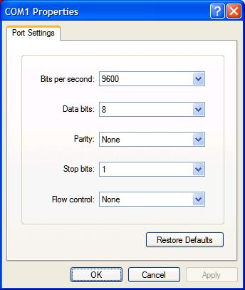
* = signal switched by the SS20 serial switch x = signal unswitched or looped by the SS20 serial switch Question: How does broadcast work? Answer: Broadcast works by connecting the transmit line from the main control port to the receive lines of multiple target ports. Note that while you can transmit to multiple devices simultaneously, you can only receive from one device at a time. Question: I can't access my target device after successfully switching from the menu. Answer: If you can access the switch menu after connecting your device, chances are you're wiring is correct. You may need to disable flow control or set the baud rate on your target device. Remember that you need to exit from the menu before the target is selected and switching actually occurs. Question: What are the default settings? Answer: Using a straight-through cable from your PC serial port or USB-serial adapter, you can connect with 9600 baud, 8 data bits, No Parity, and 1 stop bit.
Question: Can you develop custom firmware for my application? Answer: Gladly. We've done this for many customers. Our programming rate is $75/hour. After we agree on a -very specific- project description, we can send you an estimate of the time involved to code, debug and test. Question: Does the switch affect cable length? How long can I run an RS-232 cable? Answer: RS-232 transmission distances depend on cabling, baud rate, and noise. You may get 1km with low baud rates, good termination and shielded cables, but only 30m with unshielded cable in a noisy environment. The switch is essentially passive; it doesn't significantly affect transmission characteristics. Question: Can you develop custom hardware for my application? Answer: Gladly. We've done this for many customers. Please call with your requirements
If we haven't answered your questions here, please call (408) 330-5599 or send us an email. We'll be glad to help. © Digital Loggers, Inc. 2005. |

